Cross-Vendor IPsec

Most admins are well aware of IPsec, the powerful protocol used to encrypt network traffic over TCP/IP networks. IPsec is often used with VPN connections to join remote LANs through a private tunnel over the Internet.
The first RFCs on IPsec were drafted during the development of IPv6 and date back to 1995. The current version is described by RFC 4301 and later RFCs. The IPsec specification refers to a number of other supporting protocols. Another protocol known as the Internet Key Exchange Protocol (IKE) lets the user avoid having to set the key randomly with each session; the first RFC relating to IKE dates back to 1998, and the current version IKEv2 is detailed by RFC 5996. Various features were added to IKE through the years to support enhancements such as Challenge Response authentication.
Implementations of the IPsec and IKE are available in various firewall products, network components, and operating systems. Despite the long, standards-based history of IPsec, different vendors implement their IPsec tools in different ways, leading to occasional complications when the two ends of the tunnel are using dissimilar implementations. I decided to try connecting several IPsec alternatives to see which versions worked best (and worst) together. My tests included the following:
- Kame/Racoon on Mac OS X and Linux
- Solaris 10
- Windows Server 2008
- Cisco-Router with IOS 12
- Juniper SRX
- Checkpoint R70
- Fortinet Fortigate
The good news is that VPN connections were successfully established between all the candidates. This article looks at the details of configuring the individual components and points out the pitfalls associated with the various pairings. Along the way, you’ll get a glimpse at what it is like to configure each of these IPsec tools, in case you happen to be searching for your own IPsec solution.
Configuration Steps for IKE
An IPsec connection can run in tunnel mode (multiple LANs are connected with gateways that encrypt the traffic between the LANs) or in transport mode (with traffic between two individual hosts).
You can use IPsec for encryption and/or authentication. The encryption feature uses ESP (Encapsulating Security Payload) and authentication uses AH (Authentication Header). In the case of authenticated and encrypted packets, IPsec first creates the authentication header and puts it at the start of the packet before encrypting the whole packet and encapsulating it in ESP.
Authentication is handled by a hash of a key and the packet. The entity at the other end, which has the key, can perform computations to make sure the packet is unchanged and originated from the authenticated sender. A symmetric algorithm such as AES or Blowfish is used for encryption. The choice of the key for authentication and encryption, and the choice of the hash and encryption algorithms, can be handled through a manual configuration (Manual IPsec) or by using the IKE protocol.
In the case of IKE, the two sides negotiate the algorithms in two phases. In Phase 1, the two sides mutually authenticate using a fixed key or X.509 certificates (new extensions with other approaches now also exist). In this phase, a hash and an encryption algorithm are chosen from a configured selection. Optionally, the validity period for the connection can be set (Security Association SA), as can PFS (Perfect Forwarding Secrecy). PFS is a property that ensures the session key used to send the payload data cannot be computed from the IKE SA keys when one of the IKE keys has been compromised.
Once the IKE SA is agreed upon, the keys of hashes for the IPsec connection are negotiated in Phase 2. Again, a (far shorter) validity period for the keys is defined in units of time or transferred bytes, and PFS can be optionally negotiated. After completing negotiation, a kernel entry is typically created to specify that the IPsec connection will use these parameters, and the gateway encapsulates packets for the other end in an ESP, AH, or ESP+AH packet, which the other end then unpacks and forwards.
Depending on the implementation, the administrator might still need to modify the IP routing setup to make sure the packets from the LAN actually end up in the tunnel. Whether or not this is necessary and which routing entries are actually needed, were points of confusion in the lab. In any case, be sure to enable the traffic in the firewall ruleset.
Test Setup
Each IPsec gateway was given its own LAN for the test, and all of them were directly connected via a network (Figure 1).
 Figure 1: A private network is the test setting for all of the IPsec candidates.
The authentication method I chose was a fixed password, although the configuration between the Cisco router and Solaris originally used a certificate, until I discovered how to create the hex string that Solaris expects as the PSK from the password of test123 .
I set the encryption algorithm for the first negotiation phase to 3DES and the hash algorithm for authentication was SHA1. The setting for PFS was set to group 2 (1024-bit). These parameters were not chosen for reasons for security but for reasons of compatibility, because older implementations failed to support, say, 256-bit AES for Phase 1, and because it was unclear at the start of the test which implementation could handle which algorithm or PFS groups.
In Phase 2, I wanted to use AEA256, SHA1, and PFS2, and this actually worked with just two exceptions. Although the Cisco router available that was available has hardware support for 3DES, it doesn’t support AES; this meant I had to revert to 3DES. As you will learn later in this article, Windows 2008 doesn’t support PFS for Phase 2 in the simple graphical configuration.
Kame/Racoon
Racoon is “…an IKE daemon for automatically keying IPsec connections.” [1] The Racoon daemon was originally developed as part of the Kame project [2] and is now part of the IPsec-Tools collection available on many Linux systems. Because Racoon supports fairly verbose logging of the parameters set at the start of the negotiations in debug mode, it is useful for troubleshooting, which is why I chose it as my reference implementation. All of the candidates successfully connected to Racoon first.
Three files were used for the configuration:
- racoon.conf contains the encryption and hash algorithms for Phase 1 and Phase 2, and the PFS and lifetime settings for the keys. This file maps the Phase 1 parameters to an correspondent entity, which can be an IP address or a distinguished name from a certificate. In Phase 2, net blocks (optionally ports) that are valid for the Phase 2 algorithms and parameters are specified.
- Because the configuration uses fixed passwords (preshared keys, or PSKs for short), you need a place to store this information. psk.txt maps the IP addresses of the correspondents to the passwords. Passwords can be specified in the clear or as hex strings.
- You need to store the IPsec policy, which contains rules that define which packets should be sent down the IPsec tunnel negotiated by Racoon, or from which source packets are expected to exit the tunnel. You can do this quite easily at the command line with the setkey command, but it is more practical to store the policy in a setkey script. The rules contain source and target IP address ranges, protocols and port numbers, the direction (incoming or outgoing), and a statement stating whether ESP, AH, or both should be used. You can also tell Racoon to generate the policy automatically following the negotiation phase.
Listings 1 and 2 show the configuration between the Racoon network and the network behind the Juniper firewall.
Listing 1: racoon.conf
01 path pre_shared_key "/etc/racoon/psk.txt";
02 remote 192.168.1.31 {
03   exchange_mode main;
04   proposal {
05     encryption_algorithm 3des;
06     hash_algorithm sha1;
07     authentication_algorithm pre_shared_key;
08     dh_group modp1024;
09   }
10   generate_policy off;
11 }
12
13 sainfo address 192.168.2.0/24 any address 172.16.0.0/16 any {
14   pfs_group modp1024;
15   encryption_algorithm aes256;
16   authentication_algorithm hmac_sha1;
17   compression_algorithm deflate;
18 }
Listing 2: setkey Script
01 #! /usr/sbin/setkey -f
02
03 flush;
04 spdflush;
05
06 spdadd 192.168.2.0/24 172.16.0.0/16 any -P out IPsec esp/tunnel/192.168.1.7-192.168.1.31/require;
07
08 spdadd 172.16.0.0/16 192.168.2.0/24 any -P in IPsec esp/tunnel/192.168.1.31-192.168.1.7/require;
Racoon lets you specify multiple, comma-separated algorithms at any position. The example doesn’t specify a key lifetime. Before you launch Racoon, you need to install the policy, otherwise the key/connection mappings in the kernel will not occur. The policy installation is typically handled in the init scripts.
To troubleshoot a connection attempt, it is a good idea to launch Racoon in the foreground with the -F option. This sends output to the command line, indicating whether or not the connections are negotiated in Phase 1 and 2. If something goes wrong, the log will not help; in this case, you need to set the -d option to make Racoon more verbose. Most of the output is informative but doesn’t help you with troubleshooting. You need to find the lines that let you compare the local configuration with the parameters offered at the other end of the connection (see Listing 3).
Listing 3: Debugging
01 2011-01-28 17:31:40: [6694] DEBUG: Compared: DB:Peer
02 2011-01-28 17:31:40: [6694] DEBUG: (lifetime = 28800:28800)
03 2011-01-28 17:31:40: [6694] DEBUG: (lifebyte = 0:0)
04 2011-01-28 17:31:40: [6694] DEBUG: enctype = 7:7
05 2011-01-28 17:31:40: [6694] DEBUG: (encklen = 128:128)
06 2011-01-28 17:31:40: [6694] DEBUG: hashtype = SHA:SHA
07 2011-01-28 17:31:40: [6694] DEBUG: authmethod = pre-shared key:pre-shared key
08 2011-01-28 17:31:40: [6694] DEBUG: dh_group = 1024-bit MODP group:1024-bit MODP group
09 2011-01-28 17:31:40: [6694] DEBUG: an acceptable proposal found.
10 2011-01-28 17:31:40: [6694] DEBUG: hmac(modp1024)
As you can see in the listing, everything matches, so you can continue. The encryption algorithms are AES, shown as a number. The DB:Peer search string gives you the quickest approach to finding the information you need in the comprehensive log.
Solaris
Next I tried the built-in IPsec features in Solaris 10. I dropped the initial test with a XEN-HVM virtual environment in favor of a better-performing virtual machine based on VirtualBox.
Solaris also splits up the configuration into multiple files:
- /etc/inet/IPsecinit.conf: Contains the policy, like the setkey script on Kame/Racoon; however, the file also contains the algorithms for Phase 2. A tunnel interface is also typically configured.
- /etc/hostname.ip.tunX: Typically contains the tunnel interface; although you could set this manually using the ifconfig command, it wouldn’t survive a reboot. You need a file for each connection.
- /etc/inet/ike/config : This file is similar to racoon.conf ; however, it only contains Phase 1 parameters, apart from the key lifetime definitions and the PFS group. For each correspondent, you can define parameters such as the authentication method used, the local and remote IP addresses for the connection, and the algorithms. In contrast to Racoon, you can also set generic parameters for all of your connections (for example, if you want to encrypt all Phase 1 connections with 3DES) and just overwrite any parameters that do not match a specific case on an individual basis. The ability to assign names to connections is useful for troubleshooting.
- /etc/inet/ike/secret/ike.preshared : Storage location for preset passwords. This file contains the password as a hex string, which you need to generate from the clear text password using od .
The tunnel definition looks like the following (this example is for the connection to Racoon):
192.168.60.254 192.168.2.23 tsrc 192.168.1.105 tdst 192.168.1.7 router up
A summarized version of /etc/inet/ike/config for the same partner would look something like Listing 4.
Listing 4: /etc/inet/ike/config
02 p1_nonce_len 20
03 p1_xform { auth_method preshared oakley_group 2 auth_alg sha encr_alg 3des }
04 p2_pfs 2
05 {
06   label "racoon"
07   local_id_type ipv4
08   local_addr 192.168.1.105
09   remote_addr 192.168.1.7
10 }
You still need the Phase 2 definition from IPsecinit.conf :
{tunnel ip.tun1 negotiate tunnel laddr 192.168.60.0/24 raddr 192.168.2.0/24 } IPsec {encr_algs aes encr_auth_algs sha1 sa shared}and finally, the definition of the shared secret from /etc/inet/ike/secret/ike.preshared (Listing 5).
Listing 5: /etc/inet/ike/secret/ike.preshared
01 {
02   localidtype IP
03   localid 192.168.1.105
04   remoteidtype IP
05   remoteid 192.168.1.7
06   key f04e8e75162390ba9da8000cb24e8a93fb77af519ce6514260270647
07 }
In conjunction with Racoon, you can enter the hex string directly in psk.txt . Juniper SRX also offers the option of defining a hex string instead of cleartext. The key test123 converts to a hex string of 74657374313233 . You can convert a cleartext password to the required hex string using echo Password |od -tx .
Solaris 10 introduced the concept of services, which can be stopped using svcadm . For troubleshooting, it is a good idea to stop the service and start the IKE daemon manually. You also need to enable routing because the computer will be acting as a gateway. You will find the IKE daemon in /usr/lib/inet/in.iked . It accepts a -d , option to enable debugging.
In my tests, the major obstacle wasn’t configuration but routing. In contrast to Racoon, you need to make sure that an IP route to the network at the other end exits. The confusing thing for me was the fact that the IP address of the gateway on the internal side of the other LAN needs to be configured as the gateway for the route.
In combination with Racoon, you would thus need to set the gateway for the route to the 192.168.2.0/24 network to 192.168.2.23. You can assign routes permanently on Solaris and on Windows using the -p option.
Windows 2008 Server
The Windows 2008 Server configuration cost me a couple of nights sleep, although it is actually quite simple when you know how to do it. Online hints [3] and complete deletion and reconfiguration finally pointed the way to success. Before a Windows 2008 Server can act as a VPN gateway, you first need to enable IP forwarding. Additionally, you will want to install the Network Policy and Access Services.
The configuration process uses the Windows firewall, its management console plugin, or the netsh command line tool. You can define the parameters for Phase 1 and 2 in the Windows firewall generic properties. To do so, go to the IPsec Settings tab and select Advanced to set the parameters. This is also the den of the biggest pitfall to connecting to a Microsoft Server: PFS isn’t supported in Phase 2 if you use the GUI for the configuration; you either need to disable this at the other end, or use netsh ; but more of this later. You can see the parameter entries in the dialogs in Figures 2 and 3.
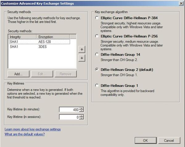 Figure 2: Phase 1 definition on Windows 2008.
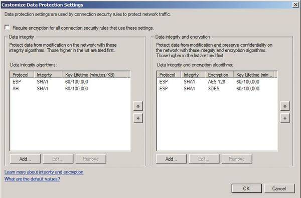 Figure 3: Phase 2 definition on Windows 2008.
The next step is to create a Connection Security Rule. Endpoint 1 will always be the LAN where the Windows Server resides, and endpoint 2 will be the LAN at the other end. The gateway IP addresses are the external addresses. The wizard that helps you create the new rule also asks for the authentication method, which you need to set to Pre Shared Key . From then on, the password is stored for all connections; in other words, you can’t choose different parameters for the encryption algorithms on an individual connection basis. Finally, you need to set a route that points to the VPN gateway’s external address for the LAN at the other end. To make sure your routing configuration survives a reboot, you again (like Solaris) need to use the -p option.
Instead of a GUI-based configuration, you can use netsh ; this also gives you the ability to choose PFS for Phase 2 or to specify individual algorithms for each connection. Listing 6 shows a sample configuration.
Listing 6: Configuration with netsh
 netsh advfirewall consec add rule name="Tunnel to racoon"
       enable=yes
       mode=tunnel
       localtunnelendpoint=192.168.1.115
       remotetunnelendpoint=192.168.1.7
       endpoint1=192.168.80.0/24
       endpoint2=192.168.2.0/24
       action=requireinrequireout
       auth1=computerpsk
       auth1psk="test123"
       qmsecmethods=esp:sha1-3des
       qmpfs=dhgroup2
If you need to create a large number of tunnels, you will probably go for scripting with netsh ; not just because of the improved granularity, but because it is a quicker tool. Troubleshooting on Windows is a difficult task because, by default, no log entries related to IPSCE connections are created in the Windows event log by default. I found an article on TechNet [4] that explained the use of auditpol.exe and solved this issue. The syntax for this is:
auditpol.exe /set /category "System" /subcategory "IPsec Driver" /success:enable /failure:enable
After entering this information, messages for successful and failed IKE negotations will appear in the Security Log. But if a connection doesn’t work, the log won’t always provide a reason.
Cisco IOS
For IOS (I used Version 12.2 in my tests), the configuration comprises six elements:
- An IKE policy, which contains the encryption algorithm, the PFS group for Phase 1, and the authentication method.
- One pre-shared key per partner.
- A lifetime for the keys negotiated in Phase 2.
- The encryption algorithm and hash algorithm for Phase 2.
- A Crypto Map for key mappings.
- An access list that defines which traffic belongs to the VPN defined in the Crypto Map.
The router I tested had a board for 3DES hardware acceleration, but although you could select AES in the configuration, this option simply led to an error, which was displayed as a comment for show run .
During negotiation of the parameters, the Cisco router didn’t offer its correspondent AES. Based on these facts, the configuration commands look like this:
crypto isakmp policy 1
 encr 3des
 authentication pre-share
 group 2
If you assign multiple policies with serial numbers, the router applies them one after another. The hash keyword in the policy lets you select MD5. SHA1 is the default.
crypto isakmp key test123 address 192.168.1.7
The following line assigns a key to the correspondent:
crypto IPsec security-association lifetime seconds 28800
The preceding line globally defines the key lifetime in Phase 2. This step is not possible on a per-connection basis. You can tell that this is Phase 2 because the line starts with crypto IPsec rather than crypto isakmp :
crypto IPsec transform-set vpn esp-3des esp-sha-hmac
This line defines the transform-set with a name of vpn , which is then referenced in the Crypto Map with the following:
crypto map vpn 10 IPsec-isakmp
 set peer 192.168.1.7
 set transform-set vpn
 set pfs group2
 match address 110
The Crypto Map maps the entries. The peer adds the key, and the router knows with whom to negotiate the connection. The transform set maps the Phase 2 parameters. The PFS group relates to Phase 2, and the last line references an access list, which then follows. If the router needs to build a tunnel to multiple parties, the index is incremented.
access-list 110 permit ip 192.168.50.0 0.0.0.255 192.168.2.0 0.0.0.255
This rule defines that the traffic between the 192.168.50.0/24 network and 192.168.2.0/24 is routed into the VPN.
Troubleshooting is just as comprehensive as with Racoon; and this means that, to uncover an error, the administrator needs to search through the mess of data to find the place where the difference between the Phase 1 and Phase 2 parameters occurs. debug crypto isakmp lets you investigate the IKE negotiation, and debug crypto IPsec the resulting IPsec packets. Otherwise, I had no issues with trying to integrate the router into the VPN. The lack of support for AES did make the Checkpoint configuration more complex.
Juniper SRX
Juniper’s SRX [5] is a Junos-based router with firewall technology added thanks to the acquisition of Netscreen. Junos also differentiates between VPNs based on policies and others based on routing. In my tests, I opted for a routing-based VPN. To allow this to happen, you first need to define a loopback interface by the name of st0 , to which an IP address is assigned; in a Juniper-only VPN, this would be the gateway for other SRX devices. Juniper devices use a proprietary protocol to find the gateways and then automatically discover routes to partners.
If you use third-party routers, you need to specify an IP address on your own LAN and map this address to a VPN. Routes to other LAN areas are then assigned a static configuration with the IP address set in this part of the configuration to tell the firewall to send these packets down this VPN tunnel.
Interfaces on a Juniper firewall are typically assigned to zones (a zone can contain multiple interfaces). Firewall rules always contain a zone from which the packet originates and a target zone. For this reason, you first need to create the zone in which the st0 interface resides and then use this in your rules. (See the configuration in Listing 7.)
Listing 7: Juniper Firewall
01 security {
02    zones {
03      security-zone vpn {
04        interfaces {
05          st0.0;
06        }
07      }
08    }
09 }
The whole Juniper configuration is extremely modular, as is reflected in the VPN definitions. These definitions include a proposal, which contains the algorithms, PFS parameters, an authentication method, and a policy, which references the proposal with the correct values, chooses between Main and Aggressive Mode for IKE negotiations and adds the pre-shared key. The final component in the VPN definition is a gateway that references the policy and an IP address at the other end. You can enable NAT traversal on the gateway if needed.
Listing 8 shows an IKE configuration with the three components.
Listing 8: Juniper Configuration, Phase 1
01 security {
02   ike {
03     proposal Phase1-3des-sha {
04       authentication-method pre-shared-keys;
05       dh-group group2;
06       authentication-algorithm sha1;
07       encryption-algorithm 3des-cbc;
08     }
09     policy test123 {
10       mode main;
11       proposals Phase1-3des-sha;
12       pre-shared-key ascii-text "$9$dQVgJiHmTF/.PO1Ehrlgoa"; ## SECRET-DATA
13     }
14     gateway remote-racoon {
15       ike-policy test123;
16       address 192.168.1.7;
17       no-nat-traversal;
18       external-interface ge-0/0/0.0;
19     }
20   }
21 }
The logical structure of the Juniper configuration lets you easily reuse individual parts of it. If you want all partners to use the same PSK and the same Phase 1 parameters, you just need to add the gateway entries after the first two entries. The policy can also reference multiple proposals that are available to the partner.
The next step involves the Phase 2 parameter., which are located in the Security | IPsec contest. The configuration comprises three sections: the proposal, which contains the Phase 2 algorithms and the protocol (ESP or AH); the policy, which references a proposal and defines PFS for Phase 2; and finally the VPN, which references the policy and assigns a gateway from the IKE definition. The definition also includes the LAN segments between which the VPN will be created; the router informs the other end of the connection of these during negotiations. For a route-based VPN, you also need to assign the loopback interface for the VPN. Listing 9 shows you the setup for this combination.
Listing 9: Juniper Configuration, Phase 2
01 security {
02   IPsec {
03     proposal aes256-sha1 {
04       protocol esp;
05       authentication-algorithm hmac-sha1-96;
06       encryption-algorithm aes-256-cbc;
07     }
08     policy pfs2-aes256-sha1 {
09       perfect-forward-secrecy {
10         keys group2;
11       }
12       proposals aes256-sha1;
13     }
14     vpn racoonvpn {
15       bind-interface st0.0;
16       ike {
17         gateway racoon;
18         proxy-identity {
19           local 192.168.1.0/24;
20           remote 192.168.2.0/24;
21           service any;
22         }
23         IPsec-policy pfs2-aes256-sha1;
24       }
25     }
26   }
27 }
Again you can reuse the proposal and the policy. Assuming the values stay the same, you only need to add the VPN entries.
The next-to-last step in the configuration is to add a security policy. Juniper’s zone-based concept uses two rules to specify policies:
- From the VPN zone to the zone with the internal LAN.
- In the opposite direction, from the internal LAN zone into the VPN zone.
Additionally, you need to enable IKE on the external side of the incoming interface to tell the firewall to process IKE requests. This definition occurs in the context of the “outer” zone (typically untrusted) for each interface that you want to accept IKE requests. The rule is shown in Listing 10.
Listing 10: Firewall Rules for Juniper
01 security {
02   from-zone vpn to-zone trust {
03     match {
04       source-address remotelan;
05       destination-address trustnet;
06       application any;
07     }
08     then {
09       permit;
10     }
11   }
12   from-zone trust to-zone vpn {
13     match {
14       source-address trustnet;
15       destination-address remotelan;
16       application any;
17     }
18     then {
19       permit;
20     }
21   }
22 }
You need to define trustnet and remotelan in the zone address book because Juniper only processes network objects as address book entries.
The traceoptions instruction below Security | IKE enables debugging. file filename specifies the name of a logfile, while flag ike starts debugging. The logfile ends up on the SRX router filesystem and can be viewed there by typing show log filename (or using less if you switch to the Unix prompt at the Juniper command line.) Below the Security | IPsec context, you can enable traceoptions to log lost packets or changes to the security associations. The resulting logfile will show you that an error has occurred, but in contrast to Cisco, Racoon, or Solaris, you won’t find out why.
Checkpoint FireWall-1
Checkpoint’s VPN [6] was one of the first commercial implementations on the market. After a proprietary start, the Israeli company soon began to implement the IETF standards. Just like the other options, Checkpoint offers two configuration modes: Community Mode (roughly corresponds to routing mode, but you don’t need any routes) and traditional mode, where you can set VPN definitions for each firewall rule.
I used community mode in my tests because it is simpler to handle. I needed to create three communities because the Cisco router only supports 3DES, and because the first version of the VPNs on Windows 2008 didn’t use PFS in Phase 2. I only needed a single community for all the other candidates; the correspondents I added were Kame/Racoon, Juniper SRX, Solaris, and Fortigate. You can start by defining the Phase 1 and Phase 2 algorithms for the community (Figure 4).
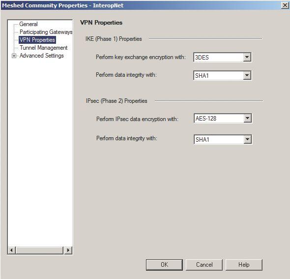 Figure 4: Defining the algorithms for Checkpoint.
You can then enter the shared secret for each correspondent in shared secret (Figure 5).
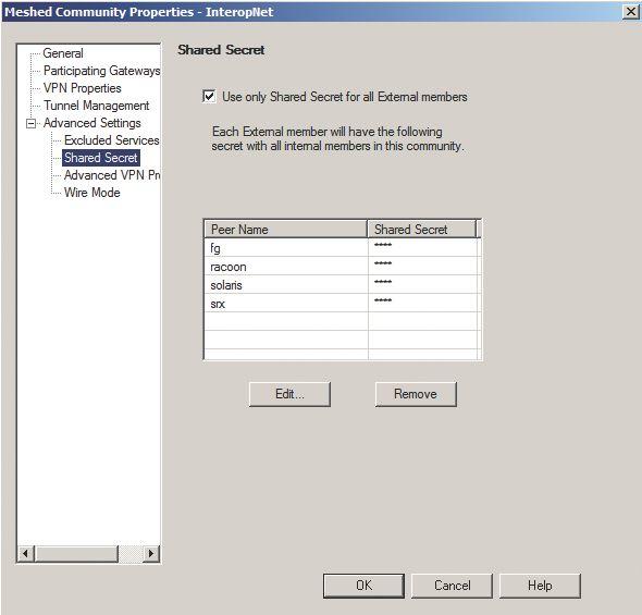 Figure 5: Entering the shared secret.
Next, go to the Advanced VPN entry to define the PFS and key lifetimes (Figure 6). To create a VPN gateway for a third-party vendor, you need to go to Interoperable Device in the community; you can do this by right-clicking below New (Figure 7).
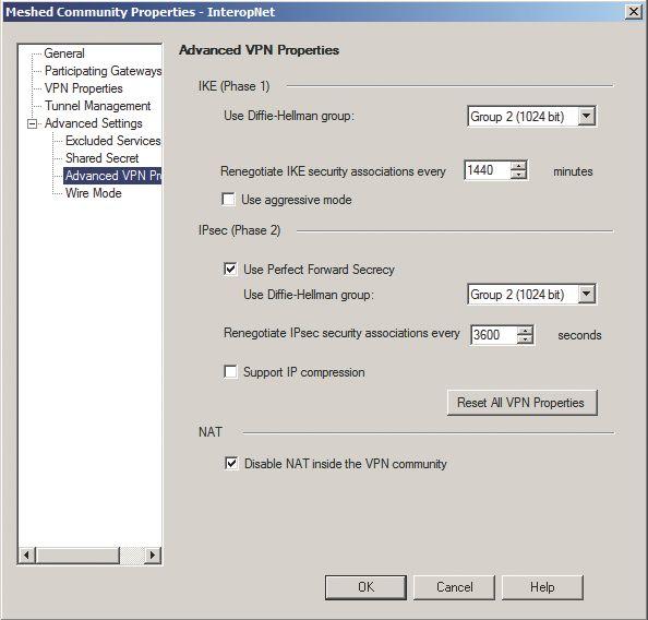 Figure 6: PFS and lifetimes.
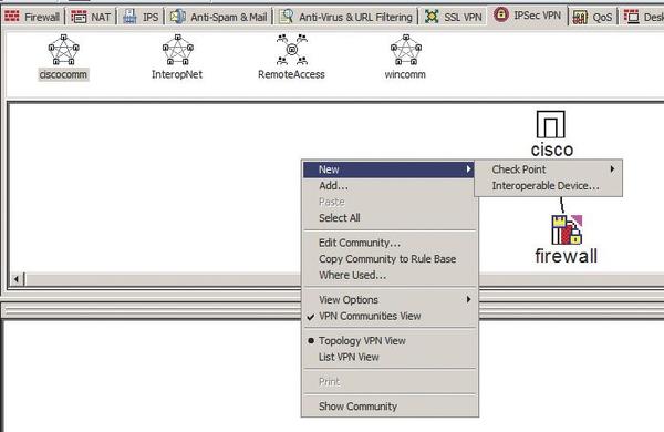 Figure 7: Creating an interoperable device.
When you create the device, you will need to assign the interfaces and their corresponding networks in Topology (the interface names don’t need to be perfect, but the IP addresses need to match.) The important thing is that the outward bound interface is declared as external) and the interface to the LAN is also declared as such. If you have more than one network segment, you must specify all of them in your definition. Because this is a firewall, you also need to add a firewall rule to allow the traffic between the two networks.
Checkpoint has the best troubleshooting support. In case of a configuration error (e.g., AES at one end and 3DES at the other), there is no need to enable debugging mode. Just check the logfile and you will see an intelligible message. If the problems are more advanced, Checkpoint offers in-depth analysis tools.
Fortinet Fortigate
You can manage a Fortigate firewall [7] via the web interface or at the command line. Just as with Juniper, you can set up a VPN in policy mode or route mode. I chose a policy VPN, for which rules and VPN definitions mesh, for the test setup with Fortigate. It took just a couple of clicks to create a VPN in the web interface; Fortigate impressed with a lean design that still supported ergonomic work.
The configuration consists of the following three steps:
- Creating the Phase 1 definition
- Creating the Phase 2 definition
- Creating a firewall rule that permits traffic on the VPN
Figure 8 shows the definition of Phase 1 of the IKE connection. Press the Advanced button to set up the individual encryption parameters. The resulting configuration is shown in Listing 11 in text format.
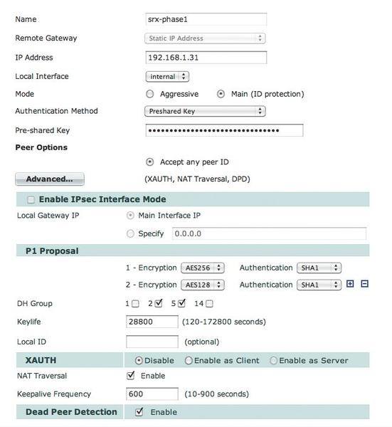 Figure 8: Creating the Phase 1 definition for Fortigate.
Listing 11: Fortigate, Phase 1
01 edit "srx-phase1"
02   set interface "internal"
03   set dhgrp 2 5
04   set proposal aes256-sha1 aes128-sha1
05   set remote-gw 192.168.1.31
06   set psksecret
         ENC kB+sdP4e109vAROdm9TRn9YIzA47T3JHPK4xVOzYu/8nc3wmqBknMZBzfHU7VRuWBF2gncDuHY1ubeCk9DU3zasHi61Izu0m6cg1cdERjgNmKKcO
07   set keepalive 600
08 next
The next step is the Phase 2 definition; it must be assigned to a Phase 1 definition (Figure 9). Just as in Phase 1, you need to click the Advanced button to get to the interesting parameters. The first attempt at a VPN definition failed because the networks between which the VPN was to be created were missing in this dialog. Listing 12 shows the corresponding configuration section. The final step is the firewall rule, and the VPN is ready (Figure 10).
Listing 12: Fortinet, Phase 2
01 edit "srx-phase2"
02   set phase1name "srx-phase1"
03   set proposal 3des-sha1 aes256-sha1
04   set dhgrp 2
05   set dst-subnet 172.16.0.0 255.255.0.0
06   set src-subnet 192.168.81.0 255.255.255.0
07 next
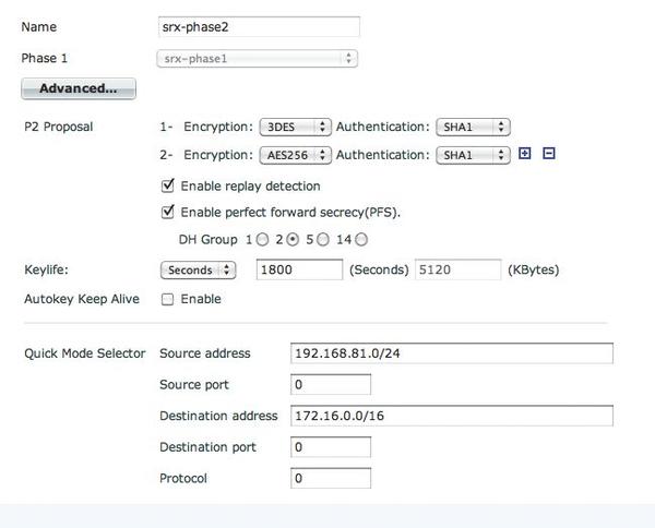 Figure 9: Creating the Phase 2 definition for Fortigate.
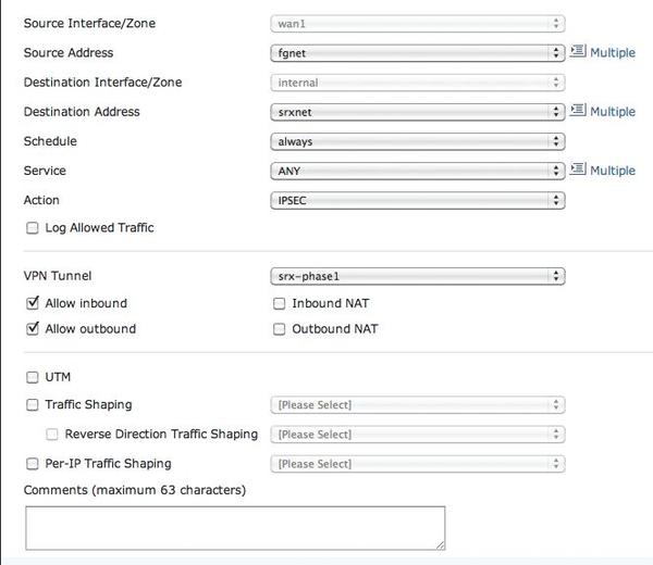 Figure 10: Defining rules for Fortigate.
fgnet contains the definition of the network behind the Fortigate device (192.168.81.0/24); srxnet the definition of the network behind the Juniper firewall (172.16.0.0/16). Select the IPsec action to be shown a dialog with a selection of the existing VPN definitions for the interface (Fortigate binds rules to zones, which are in turn bound to interfaces). The corresponding rule in text format is shown in Listing 13.
Listing 13: Fortinet, Interface Configuration
01 edit 3
02   set srcintf "wan1"
03   set dstintf "internal"
04     set srcaddr "fgnet"
05     set dstaddr "srxnet"
06   set action IPsec
07   set schedule "always"
08     set service "ANY"
09   set inbound enable
10   set outbound enable
11   set vpntunnel "srx-phase1"
12 next
The keep-alives defined in Phase 1 make debugging difficult, because they occur as messages at very frequent intervals. Under practical conditions, it could be useful to enable them, in order to trip an alert if the VPN fails. The debugging instructions seemed less than intuitive to me, and I needed to contact Fortinet for more information:
# diag debug enable
# diag debug application ike -1
If you do this, you are shown troubleshooting output similar to Racoon or Cisco, with details of the individual steps in the handshake. Because all of the connections run first attempt without any trouble, there was actually no need for troubleshooting.
One practical feature of Fortigate I would like to mention is that you can both enable the VPN connection by sending traffic, and click to enable or disable in the monitor area of the GUI.
Conclusions
In the end, all the tests were successful, although some configurations were less than intuitive. The biggest deficits were the lack of PFS in Phase 2 on Windows 2008 and routing at the other end of the tunnel on Solaris. Checkpoint was exemplary with respect to troubleshooting. Fortinet, Racoon, and Cisco also offer the administrator the information needed to find configuration errors. I occasionally forgot to define the required firewall rules for the firewalls in the lab; this led to negotiation of the phases completing successfully but without the ability to exchange encrypted packets between the networks afterwards.
The configuration I used is not intended as a recommendation from a security point of view, because the use of preshared secrets is regarded as less secure than the use of X.509 certificates. It is also more practical to use certificates issued by a centralized Certificate Authority, which makes it easier to add or delete network partners.
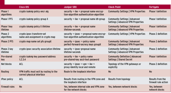
You might someday find yourself in a situation where you don’t have control over both ends of the VPN, and you’ll need to modify your own VPN gateway to reflect the situation at the other end. If so, I hope this article helps you navigate the complexities of cross-vendor IPsec. Refer to Table 1 for an overview of the parameters used in this article.
Table 1a: IPsec Parameters
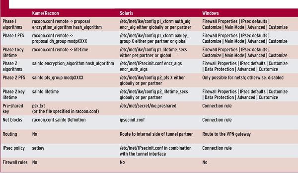
Table 1b: IPsec Parameters (cont'd)
Info
[1] IPsec tools: [http://IPsec-tools.sourceforge.net/]
[2] Kame Project: [http://www.kame.net/]
[3] Windows Server 2008 R2 and Juniper: [http://www.corelan.be/index.php/2009/01/11/IPsec-vpn-between-windows-server-2008-and-juniper-screenos/]
[4] TechNet article on IPsec debugging: [http://technet.microsoft.com/en-us/library/cc754714%28WS.10%29.aspx]
[5] Juniper SRX series: [http://www.juniper.net/us/en/products-services/security/srx-series/]
[6] Checkpoint: [http://www.checkpoint.com/]
[7] Fortinet Fortigate appliances: [http://www.fortinet.com/products/fortigate/]
The Author
Konstantin Agouros works for n.runs AG as a network security consultant. He mainly advises telecommunications providers. His book DNS/DHCP was published by Opensource Press.
Related content
-
Open source multipoint VPN with VyOS
 The VyOS Linux distribution puts network routing, firewall, and VPN functionality together and presents a fully working dynamic multipoint VPN router as an alternative or addition to a Cisco DMVPN mesh.
 -
VPN clients for Android and iOS
 Smartphones and tablets using hotspots and mobile data connections are susceptible to spying. iOS and Android each supply a tunneled VPN connection out of the box. We take a look at their apps, as well as third-party apps to see if they offer more.
 -
Hybrid public/private cloud
 Extending your data center temporarily into the cloud during a customer rush might not be easy, but it can be done, thanks to Ansible's Playbooks and some AWS scripts.
 -
Exploring Apache CloudStack
 Apache's CloudStack offers flexibility and some powerful networking features.
 -
New versions of the Endian and Sophos UTM solutions
 UTM systems combat all kinds of dangers under the policy of Unified Threat Management. The demands and expectations of customers fuel competition. Two of the most popular manufacturers – Endian and Sophos – have now released new versions of their solutions.
Subscribe to our ADMIN Newsletters
Subscribe to our Linux Newsletters
Find Linux and Open Source Jobs
Most Popular
Support Our Work
ADMIN content is made possible with support from readers like you. Please consider contributing when you've found an article to be beneficial.